Electrical wiring is an essential part of any electrical system, whether in homes, vehicles, or electronic devices. Knowing the difference between positive and negative wires is crucial for safety and functionality. Wire color coding allows electricians, engineers, and DIY enthusiasts to identify electrical paths correctly, avoid mistakes, and prevent accidents. This comprehensive guide explores all major wire colors, their meanings, applications, and safety considerations to help you work confidently with any electrical project.
Positive and negative wire colors are used to identify electrical connections clearly and safely, helping prevent wiring mistakes and electrical hazards. In most systems, red, brown, or orange wires represent positive or live connections, while black, blue, or white wires are used for negative or neutral paths, and green or green-yellow wires indicate grounding. Since wire color standards can vary by region and application, it is important to follow local electrical codes and verify polarity with proper testing tools before working on any circuit.
In this article, we discuss the topic of “positive and negative colors for wires“.
What Are Positive and Negative Wires?

Positive and negative wires refer to the two poles in an electrical circuit. The positive wire carries current from the power source to the load, while the negative wire returns it back to the source, completing the circuit. Correct identification of these wires is vital for both AC and DC circuits. Mistaking one for the other can result in short circuits, device malfunction, or even electrical shock. Understanding the role of positive and negative wires forms the foundation of safe electrical work, making color coding an indispensable tool for professionals and hobbyists alike.
Understanding Electrical Current Flow
Electrical current flows from the power source through the circuit and back again. In DC circuits, the current flows from the positive terminal to the negative terminal, while in AC circuits, the current alternates direction continuously. This flow creates a complete path that powers devices and appliances. Recognizing how current flows helps in selecting appropriate wire sizes, fuses, and protection mechanisms. Misinterpreting the flow can cause wiring issues, reduce efficiency, and damage sensitive electronics.
The Role of Wire Colors in Electrical Systems
Wire colors are a standardized method to indicate the purpose of each wire within an electrical system. They provide a quick visual guide for electricians, allowing safe installation and maintenance. Without color coding, identifying wires would require testing every conductor, increasing the chance of error. Common color conventions assign red and brown for positive, black or blue for negative, and green for grounding. By following color standards, technicians can ensure circuits function safely and efficiently while preventing accidental reversals or electrical faults.
Why Color Coding Matters for Wires
Color coding is essential for safety, efficiency, and compliance with electrical standards. Using consistent wire colors reduces the risk of wiring mistakes, electrical fires, and equipment damage. In large electrical systems, tracing a wire without color codes can be time-consuming and dangerous. For both residential and industrial applications, following standard color conventions ensures that multiple technicians can work on the same system safely. Moreover, regulatory bodies in different countries require adherence to color codes to meet safety certifications and building codes.
Common Standards for Wire Colors
Electrical standards vary globally, but some color conventions are widely recognized. In the United States, red, black, and blue usually indicate positive, whereas white or gray denotes neutral, and green signifies ground. In Europe, brown typically represents live (positive), blue is neutral, and green/yellow is grounding. Automotive wiring, battery systems, and electronics projects may use other color codes. Familiarity with local and international standards is critical for professionals who work on diverse projects, ensuring proper wiring and reducing risks.
Positive Wire Colors Explained
Positive wires carry the current from the power source to devices and components. Common colors used for positive wires include red, brown, and sometimes orange, depending on the system. In DC circuits, the red wire is almost universally recognized as positive, ensuring that current flows in the correct direction. Using the correct color coding prevents confusion during installation and reduces the risk of reversing polarity, which could damage electrical components or create a safety hazard. Positive wires must also be properly insulated to handle the voltage of the system safely.
Negative Wire Colors Explained
Negative wires complete the electrical circuit by returning current to the source. Typically, black, blue, or white wires serve as negative conductors, depending on whether the system is AC, DC, or automotive. Identifying negative wires correctly is crucial because reversing connections can result in short circuits or malfunctioning equipment. Color coding helps technicians immediately recognize the negative path without testing each wire individually. Proper labeling and adherence to standards also simplify troubleshooting in complex circuits and multi-wire systems.
Red Wire: Typical Uses and Meaning
Red wires are commonly used as positive conductors in both DC and AC systems. In automotive applications, red usually signifies a power supply to a device or accessory. In household wiring, red can indicate a secondary live wire in a 220V circuit. Red wires often carry current to switches, outlets, or devices, making them critical to circuit operation. Their bright color makes them easy to identify, reducing mistakes during installation. Always ensure that red wires are insulated and securely connected to prevent short circuits or overheating.
Black Wire: Typical Uses and Meaning
Black wires are often used as negative or live wires, depending on the electrical system type. In DC systems, black usually indicates negative polarity, while in AC household wiring, black often represents a live or “hot” wire. Black wires carry current and must be handled carefully to avoid shocks. Technicians frequently use black wires to complete circuits, connect switches, or provide power to outlets and appliances. Correct identification of black wires through color coding is essential to prevent wiring errors, equipment damage, or safety hazards.
White Wire: Common Applications in Circuits
White wires are primarily used as neutral conductors in AC circuits. Neutral wires complete the electrical path, carrying current back to the power source. In some DC systems, white may also indicate a negative or common connection. White wires help ensure circuits function safely and efficiently by providing a clear return path for current. Properly identifying white wires reduces the risk of accidental contact with live wires, which could lead to electrical shocks or short circuits. Color coding combined with labels ensures safe and reliable wiring practices.
Green Wire: Grounding and Safety
Green wires are universally recognized for grounding purposes. They do not carry current under normal operation but provide a safe path for electricity in case of a fault. Ground wires protect users and equipment from electrical shock and prevent damage from voltage surges. Green wires are often paired with yellow stripes to distinguish them further in complex wiring systems. Proper grounding is essential in all electrical setups, and correctly colored wires help ensure safety compliance in homes, vehicles, and industrial systems.
Blue Wire: When It Represents Negative

In some DC systems, blue wires are used as negative conductors. In AC wiring, blue may indicate neutral in European systems. Blue wires often appear in automotive, industrial, and electronic circuits where multiple positive and negative paths exist. Correctly identifying blue wires ensures that devices receive current in the intended direction and prevents polarity errors. Technicians rely on color coding to avoid confusion, especially in systems with multiple wires of similar gauge. Proper labeling and adherence to standards make blue wires easy to identify and safe to use.
Yellow Wire: Function and Safety Considerations
Yellow wires are often used as secondary live wires or in control circuits. They can indicate switch legs or intermediate connections in AC systems. In DC systems, yellow may sometimes serve as a positive wire or signal conductor. Because yellow is less common than red or black, it is crucial to ensure proper labeling and documentation. Misidentifying yellow wires can result in improper connections, device failure, or safety hazards. Their bright color helps technicians distinguish them from other conductors during installation or maintenance.
Brown Wire: Positive Wire Applications
Brown wires are commonly used as positive or live wires, particularly in European AC wiring systems. They carry current from the power source to devices, switches, or outlets. Brown is often paired with blue neutral wires and green/yellow ground wires for clarity and safety. In industrial systems, brown wires may also indicate phase A in three-phase circuits. Correctly identifying brown wires ensures that circuits function safely, and reduces the risk of short circuits, equipment damage, or electrical accidents.
Orange Wire: Common Uses in Electronics
Orange wires are frequently used as secondary positive wires or in specialized circuits. In electronics and control systems, orange may indicate switch legs, live connections, or intermediate voltage paths. The bright color makes it easy to distinguish from red, black, and brown wires. Orange wires often carry moderate current and require proper insulation to prevent overheating or accidental contact. Technicians rely on orange wires in complex wiring setups to simplify identification and ensure safe installation.
Gray Wire: When It Represents Neutral
Gray wires are typically used as neutral conductors in AC electrical systems, especially in Europe. They provide a return path for current back to the source, completing the circuit safely. Gray is sometimes chosen instead of white to avoid confusion in multi-wire systems or industrial installations. Correct identification of gray wires ensures proper circuit functionality and reduces the risk of electrical faults. Color coding makes it easier for electricians and DIYers to distinguish neutral conductors from live or ground wires.
How Wire Colors Differ by Region
Wire color conventions vary depending on the region and electrical standards. In the United States, red and black usually indicate positive, white or gray is neutral, and green is ground. In Europe, brown is live, blue is neutral, and green/yellow is ground. Automotive, solar, and battery systems may follow different color standards altogether. Understanding regional differences is essential for electricians, engineers, and hobbyists who work with international equipment. Adhering to local color standards ensures safety and compliance with regulations.
Wire Colors in North American Electrical Codes
In North America, the National Electrical Code (NEC) defines color standards for wiring. Black and red are often used for hot wires, white for neutral, and green or bare for ground. Blue and yellow may be used as switch legs or travelers in three-way circuits. Following NEC guidelines is mandatory for residential, commercial, and industrial installations. Compliance ensures electrical safety, simplifies inspections, and minimizes the risk of incorrect connections. Using the correct colors also makes troubleshooting much easier.
Wire Colors in European Electrical Standards
European countries follow the IEC (International Electrotechnical Commission) standard for wire color coding. Brown indicates live wires, blue is neutral, and green/yellow is for grounding. In three-phase systems, black, gray, and brown represent different phases. Proper adherence to these standards is crucial for safety, especially when installing or maintaining equipment imported from other countries. Color coding helps electricians avoid errors, maintain consistency, and prevent accidents in multi-phase and industrial electrical systems.
Identifying Positive and Negative Wires in DC Circuits
In DC circuits, positive and negative wires are crucial for ensuring devices receive correct polarity. Red usually indicates positive, and black or blue indicates negative. Reversing polarity in DC systems can damage batteries, electronics, and motors. Color coding simplifies identification, allowing technicians to connect circuits safely and efficiently. Testing with a multimeter provides an additional safety check. Proper documentation of wire colors ensures consistent understanding across different users and projects.
Identifying Positive and Negative Wires in AC Circuits
AC circuits use a different approach, as current alternates direction. Live wires (often brown or black) carry current to devices, while neutral wires (blue or white) complete the return path. Ground wires (green or green/yellow) provide safety. Color coding ensures that technicians do not mistakenly swap live and neutral connections, which could cause shocks or equipment damage. Identifying wire polarity correctly is critical during installation, maintenance, and troubleshooting of household or industrial AC circuits.
Tips for Testing Wire Polarity Safely
Testing wire polarity ensures proper connections and prevents damage or hazards. Use a digital multimeter to measure voltage and confirm positive and negative wires. Always turn off power before handling wires to avoid shocks. Label wires as you test to maintain clarity in complex systems. Using color codes along with polarity testing reduces errors and improves overall safety. Proper testing practices are essential in both residential and industrial electrical work, especially when working with unknown or old wiring.
Multimeter Use for Checking Wire Polarity
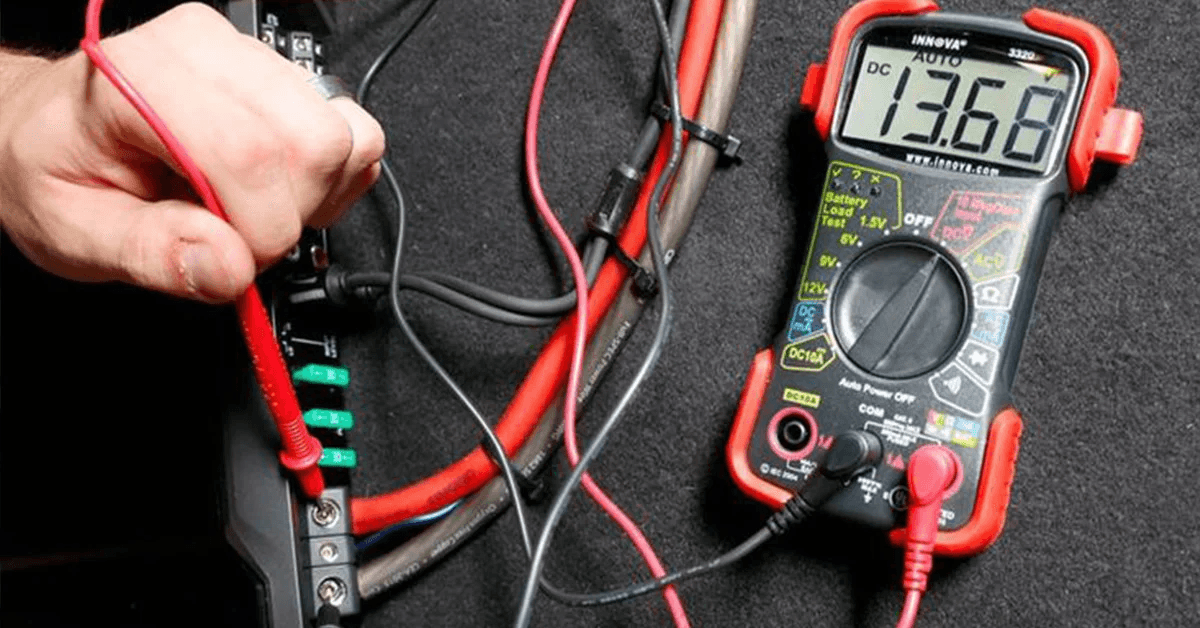
A multimeter is a versatile tool for verifying wire polarity and continuity. Set the multimeter to DC voltage mode for DC circuits, or AC mode for AC circuits. Place the probes on the wires: the positive reading identifies the positive wire, and the negative reading identifies the negative. Using a multimeter in combination with wire color codes ensures accuracy. Regular testing helps prevent short circuits, device failure, or accidental electrical shocks. Multimeters are essential for both professionals and DIY enthusiasts.
Conclusion
Understanding positive and negative wire colors is critical for safe and efficient electrical work. Proper color coding helps identify circuits quickly, reduces the risk of electrical shock, and prevents equipment damage. Different regions and applications may have varying standards, but the principles remain the same: red, brown, or orange typically indicate positive/live wires, while black, blue, or white usually indicate negative/neutral wires, and green or green/yellow is for grounding.
Whether you’re working on home wiring, automotive projects, or electronics, adhering to color codes ensures safety, reliability, and easier troubleshooting. By combining color knowledge with proper tools and testing methods, you can confidently manage any electrical system.
FAQs
1. What do red and black wires mean?
Red wires generally indicate positive or live wires, while black wires usually signify negative or hot wires, depending on whether the system is DC or AC.
2. Can wire colors differ between countries?
Yes, North America and Europe use different color standards. Always check local codes before wiring.
3. Is it safe to use a wire with the wrong color?
Using the wrong color can cause confusion, mistakes, and safety hazards. Always follow standard color coding.
4. What color is used for grounding wires?
Green or green with a yellow stripe is universally used for grounding.
5. How do I identify positive and negative wires in DC circuits?
Typically, red is positive and black or blue is negative. Use a multimeter to confirm.
6. Do AC circuits have positive and negative wires?
AC circuits have live (hot) and neutral wires instead of positive and negative. Polarity is determined by live and neutral connections.
7. Can white wires be used as negative wires?
In DC circuits, white may sometimes serve as negative. In AC circuits, white is generally neutral.
8. How can I safely test wire polarity?
Turn off power, use a multimeter, and verify voltage readings before connecting or modifying wires.
9. Are orange and yellow wires standard?
Yes, they are used as secondary positive or live wires in control, switch, and electronics circuits.
10. Why is color coding important in electrical projects?
It prevents errors, ensures safety, simplifies troubleshooting, and helps technicians work consistently across systems.
Keep an eye for more latest news & updates on premiumtechy!