A 7-wire trailer plug diagram is a visual representation that shows how each wire corresponds to a specific trailer function. It illustrates the wiring pattern for lighting, braking, charging, and grounding systems. This diagram is essential for ensuring safe towing because it helps users understand how electricity flows between the tow vehicle and the trailer. Without proper wiring, lights may fail, brakes may not engage, and safety systems can malfunction. The 7-wire setup is the most common standard for heavy-duty and multi-function trailers. For new owners and professionals alike, learning the diagram is the first step to successful trailer wiring.
A 7 wire trailer plug diagram shows how each wire is connected to essential trailer functions such as lights, electric brakes, reverse lights, grounding, and auxiliary power. It helps ensure correct wiring by following standard pin positions and color codes, reducing the risk of electrical faults. Understanding this diagram improves towing safety, simplifies troubleshooting, and ensures reliable performance for all types of trailers.
In this article, we discuss the topic of “7 wire trailer plug diagram“.
Why the 7 Wire Trailer Plug Diagram Is Important
The 7-wire trailer plug diagram is important because it ensures standardized wiring across different vehicle and trailer combinations. Proper connections guarantee that brake lights, turn signals, and running lights function correctly on the road. It also ensures that electric brakes and auxiliary power systems work without failure. Using the diagram reduces wiring mistakes and prevents electrical shorts or overloads. This diagram creates a universal reference, making repairs easier across various trailer types. Ultimately, it promotes towing safety, legal compliance, and consistent performance.
Components Included in a 7 Wire Trailer Plug Diagram
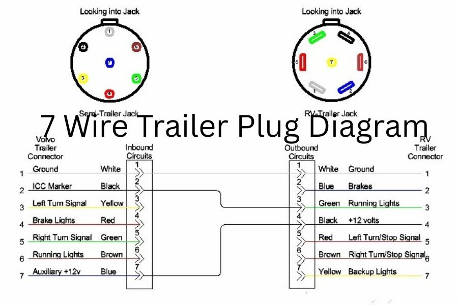
A standard 7-wire trailer plug diagram includes seven wires, each assigned to a unique function such as brake lights, turn signals, electric brakes, reverse lights, and ground. The diagram typically shows color codes for quick identification and connection. It also includes pin positions inside the plug housing to prevent mismatched wiring. Some diagrams feature additional details, such as fuse locations and auxiliary circuits. Understanding these components enables users to install, repair, or upgrade wiring systems with confidence. Each component plays a key role in proper electrical communication between the trailer and the towing vehicle.
How to Read a 7 Wire Trailer Plug Diagram
Reading a 7-wire trailer plug diagram requires identifying each pin and tracing its corresponding wire color and function. Most diagrams are drawn from the rear view of the plug, showing the pins in their physical arrangement. You start by locating the ground pin, which is usually the largest or most distinctive. Next, you identify lighting and brake wiring paths. Reading the diagram carefully prevents cross-wiring and electrical failures. With practice, users can easily decode any trailer plug diagram and perform accurate wiring tasks. Understanding the diagram saves time and prevents costly mistakes.
Standard Color Codes in a 7 Wire Trailer Plug
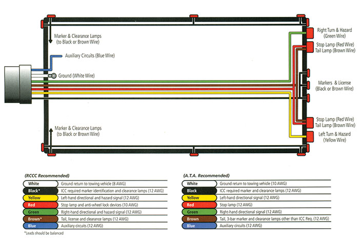
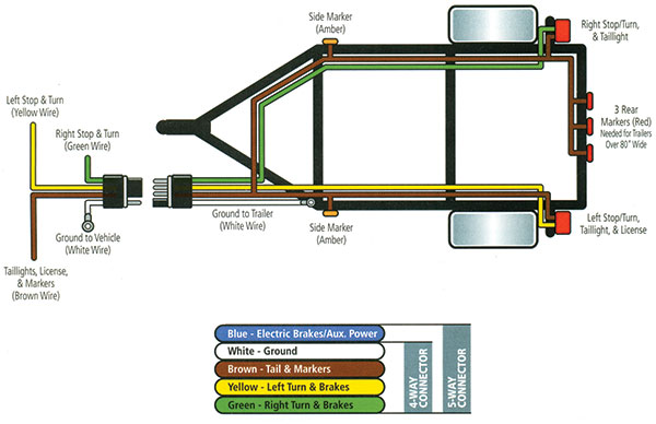
Standard color codes help simplify wiring by assigning each function a unique color. In North America, these colors are mostly universal: white for ground, black for battery power, blue for electric brakes, yellow for reverse, brown for running lights, green for right turn, and red for left turn. Following these standard colors makes installations consistent across various trailers. However, older or foreign trailers may use non-standard colors, requiring extra caution. These color codes ensure quick identification during repairs and upgrades. Memorizing them helps users work more efficiently.
7 Wire Trailer Plug Diagram for RVs
RVs require a 7-wire trailer plug diagram because they often include additional electrical features such as battery charging, interior lighting, or backup cameras. The diagram ensures proper power delivery from the tow vehicle to the RV’s systems. RV wiring must be stable to avoid failures during long-distance travel. Because RVs are heavier, electric brake wiring must be precise to ensure safe stopping. The 7-wire setup also supports reliable lighting, which is essential for nighttime towing. For RV owners, understanding this diagram helps maintain performance and safety on the road.
7 Wire Trailer Plug Diagram for Utility Trailers
Utility trailers frequently use 7-wire plugs for tasks requiring electric braking and consistent lighting. The diagram helps users wire the trailer for transporting tools, equipment, or heavy loads. Proper wiring ensures the trailer’s lights remain visible, especially during nighttime or highway driving. Electric brake circuits in the diagram offer additional control for heavier loads. Utility trailers often experience rough use, so the diagram helps identify and fix wiring issues quickly. With correct wiring, a utility trailer becomes safer, more reliable, and compliant with towing laws.
7 Wire Trailer Plug Diagram for Boat Trailers
Boat trailers benefit from the 7-wire diagram because they often operate in wet environments where electrical systems are vulnerable. The diagram helps ensure proper waterproof wiring configuration to avoid corrosion and shorts. Electric brakes, especially surge or hydraulic systems, require correct wiring alignment. Boat trailers also use reverse circuit wiring to disable brakes during backing maneuvers. The diagram ensures that lights function even after repeated water exposure. Understanding this wiring layout helps prevent electrical failures at boat ramps or on highways. Reliable wiring is crucial for safe transport of boats.
The Purpose of Each Wire in a 7 Wire Trailer Plug
Each wire in a 7-wire trailer plug serves a unique purpose, making the system fully functional and safe. The ground wire completes the circuit, while running light, brake light, and turn signals enhance visibility. Electric brake wiring connects to the tow vehicle’s brake controller for smooth stopping. Auxiliary power wiring supports battery charging or accessories. Reverse light wiring improves rear visibility during reversing. Every wire works together to create a complete towing system. Understanding each function makes troubleshooting easier and ensures proper operation.
Wiring Functions Explained in a 7 Wire Setup
In a 7-wire setup, each function is assigned to a specific pin and color code, creating an organized electrical pathway. Running lights illuminate the trailer at night, while turn signals communicate directional movement. Stop light wiring activates when braking, improving safety. Electric brake wiring allows the trailer to slow down in sync with the vehicle. Auxiliary power wiring keeps onboard batteries charged. Reverse lights provide illumination when backing up. These functions create a complete electrical system essential for safe towing.
Differences Between 4-Pin, 5-Pin, and 7-Pin Trailer Plugs
4-pin plugs handle basic lighting functions—running lights, left and right turn signals, and brake lights. 5-pin plugs add a reverse or brake lockout function for boat trailers. The 7-pin plug, however, includes all these features plus electric brakes and auxiliary power. This makes it suitable for heavy-duty and multi-system trailers. The 7-pin system offers greater versatility and is required for most modern towing setups. Understanding these differences helps users choose the right plug for their trailer type. The 7-pin remains the most comprehensive and widely used option.
7 Wire Trailer Plug Diagram for Electric Brakes
Electric brakes rely heavily on correct wiring as shown in the 7-wire diagram. The blue wire controls brake activation from the brake controller inside the tow vehicle. Proper wiring ensures consistent brake force, especially on heavy trailers. Incorrect wiring may cause brakes to lock or fail, creating a danger on the road. Electric brake circuits must be securely grounded to avoid interruptions. The diagram provides a clear reference to ensuring all brake components receive stable electrical signals. Good brake wiring ensures smooth, safe towing.
7 Wire Trailer Plug Diagram for Brake Controller
A brake controller connects to the trailer’s electric brakes through the blue wire in the 7-wire plug. The diagram outlines how signals are transmitted from the vehicle’s brake pedal to the trailer brakes. This system ensures synchronized braking, especially during sudden stops. Proper wiring improves stability, reduces trailer sway, and prevents over-braking. Many modern controllers require auxiliary power wiring to operate internal sensors. Following the diagram ensures correct installation and full controller functionality. Safe towing depends on a properly wired brake controller system.
Common Issues in 7 Wire Trailer Plug Wiring
Common issues include broken wires, corroded terminals, loose connections, and incorrect color matching. These problems often lead to flickering lights, non-working brakes, or shorts. Moisture can enter the plug housing, causing rust that disrupts electrical flow. Wires may also wear out from friction or exposure to weather. Incorrect wiring during installation is another frequent issue. Identifying these problems early prevents electrical failures during towing. Using the 7-wire diagram helps diagnose and fix such issues efficiently.
How to Fix Wiring Problems Using a 7 Wire Trailer Plug Diagram
The diagram provides a clear guide for identifying damaged or misconnected wires. Start by checking each wire for continuity and comparing its placement to the diagram. Replace frayed or corroded wires immediately. Verify that each pin corresponds to its correct function. Clean terminals using electrical cleaner to restore proper conductivity. If color codes don’t match, label wires according to the diagram. This systematic approach ensures that wiring is restored to proper working condition. The diagram remains the key reference point for all troubleshooting.
Tools Needed to Use a 7 Wire Trailer Plug Diagram
Essential tools include wire strippers, crimping pliers, multimeters, electrical tape, and heat-shrink tubing. A test light helps confirm proper wiring functions. Screwdrivers and socket wrenches are needed for plug disassembly. Some installations may require soldering tools for stronger connections. A wiring diagram should always be kept on hand during work. With the right tools, wiring becomes safer and more accurate. Proper equipment ensures durable and reliable electrical connections.
How to Test a 7 Wire Trailer Plug Connection
Testing requires a multimeter or trailer light tester. Begin by verifying the ground connection, then check each lighting function. Apply vehicle brakes and turn signals to confirm proper responses. Electric brake wiring should show voltage changes when the brake controller is activated. Auxiliary power should deliver a steady 12V supply. Testing ensures all circuits are live and working correctly. Regular testing helps catch problems before towing long distances.
Safety Tips When Wiring a 7 Wire Trailer Plug
Always disconnect the vehicle battery before wiring to avoid electrical shocks or shorts. Use heat-shrink tubing for insulated connections. Avoid routing wires near sharp edges or moving parts. Ensure the ground wire is securely connected to a clean metal surface. Never mix wire color codes without labeling them. Use waterproof connectors in wet environments. Following these precautions ensures safe, long-lasting wiring connections and prevents roadside electrical failures.
7 Wire Trailer Plug Diagram for Commercial Trailers
Commercial trailers require a 7-wire diagram due to higher electrical demands. These trailers often include heavy electric braking systems and additional lighting. The diagram ensures proper wiring for long-distance freight and industrial cargo. Auxiliary power wiring may support liftgates or internal lights. Because commercial trailers work in demanding environments, wiring must be precise and durable. Understanding the diagram helps fleet operators maintain compliance and safety standards.
Wiring a 7 Wire Trailer Plug for LED Lights
LED trailer lights require stable voltage, making proper wiring essential. The 7-wire diagram ensures that LED brake lights, turn signals, and markers receive the correct current. LEDs draw less power, reducing strain on wiring systems. However, improper grounding may cause flickering or malfunctioning. Using the diagram ensures consistent wiring for LED upgrades. Many trailers switch to LEDs for improved visibility and lower maintenance.
7 Wire Trailer Plug Diagram for Gooseneck Trailers
Gooseneck trailers often carry heavy loads, making electric brake wiring a priority. The 7-wire diagram ensures proper communication between the truck and trailer. Auxiliary power may support interior lighting or battery charging for livestock trailers. Gooseneck trailers also require reliable running lights for night visibility. The diagram helps ensure that all lighting and braking systems work flawlessly. Proper wiring improves safety, especially when towing large equipment.
Heavy-Duty 7 Wire Trailer Plug Diagram Explained
Heavy-duty trailers require thicker wires and stronger connectors due to higher current flow. The diagram remains the same but may specify larger wire gauges. These trailers rely heavily on electric brakes and auxiliary systems. The diagram ensures correct wiring even under demanding conditions. Industrial-grade plugs improve durability in harsh environments. Following the heavy-duty diagram prevents overheating and electrical failure.
7 Wire Trailer Plug Diagram for Horse Trailers
Horse trailers require reliable wiring to protect animals during transport. The 7-wire diagram ensures stable lighting and braking performance. Auxiliary power may be used for fans or interior lights. Electric brakes help maintain smooth stops to reduce stress on horses. Backup lights improve visibility during nighttime loading. Proper wiring ensures the safety and comfort of the animals. Following the diagram prevents dangerous electrical issues on the road.
Step-by-Step Guide to Wiring a 7 Wire Trailer Plug
Start by identifying and stripping each wire according to the color codes. Match the wires to the correct pins on the plug. Secure connections with crimping pliers and heat-shrink tubing. Attach the ground wire to clean metal. Test each function before securing the plug housing. Use electrical tape for added insulation. Following the diagram step by step ensures an accurate and reliable wiring job.
7 Wire Trailer Plug Diagram for Breakaway Kits
Breakaway systems require proper wiring to ensure automatic brake activation if the trailer disconnects. The diagram shows how the breakaway battery connects to the electric brakes. Auxiliary wiring supplies power to charge the breakaway battery. Proper wiring ensures safety during emergencies. Faulty breakaway wiring can lead to legal issues and unsafe towing. Using the diagram guarantees proper installation for maximum protection.
Troubleshooting a Faulty 7 Wire Trailer Plug
Troubleshooting starts with checking the ground connection. Next, test each circuit using a multimeter. Look for frayed wires, corrosion, or loose terminals. Identify mismatched color codes and correct them according to the diagram. Replace damaged plugs or connectors immediately. Clean and secure all wiring to prevent recurrence. Using the diagram simplifies the troubleshooting process.
Common Mistakes When Reading a 7 Wire Trailer Plug Diagram
Common mistakes include misinterpreting the plug orientation, assuming color codes match universal standards, or wiring the brake circuit incorrectly. Users may confuse the auxiliary wire with the reverse light wire. Poor grounding is another frequent error. Reading the diagram carefully prevents these issues. Double-checking connections avoids costly rewiring later.
7 Wire Trailer Plug Diagram for European Trailers
European trailers often use different wiring standards and color codes. The 7-wire diagram adapts these differences to ensure compatibility with North American vehicles. Reverse and fog lights may be wired differently. European trailers may also require adapters to use U.S.-standard plugs. Understanding these differences helps avoid mismatched wiring. The diagram ensures smooth cross-country towing.
Round vs. Flat 7 Wire Trailer Plug Diagrams
Round plugs are common in heavy-duty trailers, while flat plugs are used for lighter setups. The diagram remains similar, but pin positions differ. Round plugs offer better durability and weather resistance. Flat plugs are easier to install but less rugged. Understanding the diagram helps users choose and wire the right plug style. Both types maintain the same core functionality.
Color Mismatches in a 7 Wire Trailer Plug Diagram
Older trailers or DIY builds may not follow standard color codes. This can create confusion when wiring or repairing the system. When colors do not match, users must refer strictly to the diagram rather than relying on assumptions. Labeling wires helps prevent errors. A continuity test confirms each wire’s function. This ensures correct connections despite mismatched colors.
Upgrading to a 7 Wire Trailer Plug
Upgrading from a 4-pin or 5-pin plug to a 7-pin setup allows for electric brake and auxiliary power capabilities. The diagram guides users through adding the necessary wires. This upgrade improves safety and expands trailer functionality. It also ensures compatibility with modern towing vehicles. Proper grounding and correct pin placement are essential. Upgrading enhances long-term towing reliability.
How Weather Affects Your 7 Wire Trailer Plug Wiring
Moisture can cause corrosion inside the plug, while extreme heat may weaken insulation. Cold weather can make wires brittle. Understanding weather effects helps users protect wiring by using dielectric grease, waterproof connectors, and sealed housings. The diagram helps identify vulnerable areas needing extra protection. Maintaining weather-resistant wiring improves plug lifespan. Regular inspections help prevent weather-related failures.
7 Wire Trailer Plug Diagram for Off-Road Trailers
Off-road trailers require reinforced wiring due to tough terrain and vibrations. The 7-wire diagram ensures proper lighting and brake performance during rugged travel. Heavy-duty insulation and secure grounding are essential. Auxiliary power may support off-grid batteries or equipment. Proper wiring ensures reliability on uneven trails. The diagram makes off-road installations straightforward and safe.
7 Blade vs. 7 Pin Trailer Plug Diagrams
A 7-blade plug uses flat, blade-style terminals, while a 7-pin uses round terminals. Although physically different, both follow the same wiring functions. The diagram illustrates the differences in pin layout. Blade plugs are more common in North America due to durability. Pin plugs may be used in specialized applications. Understanding these differences prevents incompatible connections.
How to Clean a 7 Wire Trailer Plug
Cleaning involves using electrical contact cleaner and a small wire brush. Remove corrosion from pins and apply dielectric grease to prevent moisture buildup. Inspect wires for dirt or damage. Cleaning maintains strong electrical conductivity. Regular maintenance helps avoid flickering lights and brake issues. The diagram helps identify which pins need the most attention.
Diagnosing Short Circuits Using a 7 Wire Trailer Plug Diagram
A short circuit typically occurs when wires touch or insulation wears off. Using the diagram, identify affected circuits and test for continuity. Inspect each wire path carefully. Replace damaged wires and secure them with protective tubing. Correct grounding prevents future shorts. The diagram makes it easier to trace electrical paths and locate problems quickly.
Installing a 7 Wire Trailer Plug on a Truck
Installation requires mounting the plug near the hitch and wiring it into the vehicle’s electrical system. The 7-wire diagram shows which signal wires connect to brake lights, turn signals, and power circuits. Grounding must be secured to the vehicle chassis. Electric brake controller wiring connects through the blue wire. Testing ensures proper operation before towing. Proper installation guarantees safe and reliable performance.
7 Wire Trailer Plug Diagram for Towing Packages
Factory towing packages often include pre-wired connectors that follow the 7-wire diagram. These setups simplify installation for users. The diagram ensures proper integration with brake controllers and lighting systems. Towing packages also offer fused circuits for protection. Understanding the diagram allows users to add accessories or upgrade components. It ensures compatibility with different trailer types.
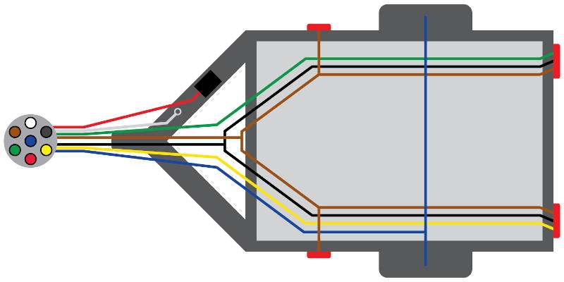
Trailer Lighting Guide Using the 7 Wire Trailer Plug Diagram
Trailer lighting systems rely heavily on correct wiring from the diagram. Running lights, brake lights, turn signals, and side markers must function properly. The ground wire ensures consistent brightness. Faulty wiring can cause dim or flickering lights. Using the diagram ensures correct routing of all lighting circuits. It improves night visibility and road safety.
Understanding Ground and Power Wires in the 7 Wire Diagram
The ground wire completes the electrical circuit, making it essential for every function. Poor grounding causes most wiring issues. The power wire delivers 12V to auxiliary systems and battery chargers. The diagram shows how these wires integrate into the system. Proper grounding ensures strong lighting and brake performance. Understanding these wires prevents electrical instability.
How to Replace a 7 Wire Trailer Plug
Start by cutting off the damaged plug and stripping back insulation to reveal clean wire ends. Match each wire to the correct pin using the diagram. Secure connections with crimp terminals and heat-shrink tubing. Test all functions before final assembly. Replacing a plug restores electrical reliability. The diagram ensures accurate rewiring.
Adapter Guide: Using a 7 Wire Trailer Plug with Other Plugs
Adapters allow 7-pin plugs to connect to 4-pin, 5-pin, or 6-pin systems. The diagram guides users in understanding which functions are lost or modified when using adapters. Electric brakes and auxiliary power may not work with smaller plugs. Adapters are useful for temporary connections. Understanding wiring differences ensures safe towing.
7 Wire Trailer Plug Diagram for Custom Trailer Builds
Custom-built trailers often require personalized wiring for accessories or additional lights. The diagram provides a foundation for connecting essential functions. Users can add circuits for interior lights, chargers, or cameras. Proper wiring ensures that custom features function safely. The diagram maintains consistency even in unique builds. This makes troubleshooting easier in the future.
How to Prevent Corrosion in 7 Wire Trailer Plugs
Prevent corrosion by using dielectric grease, waterproof covers, and rust-resistant connectors. Keep plugs off the ground when not in use. Clean and dry the plug after exposure to rain or saltwater. Corrosion disrupts electrical signals and causes failures. Using the diagram helps identify which areas require extra protection. Preventing corrosion extends plug lifespan.
7 Wire Trailer Plug Diagram for Agricultural Trailers
Agricultural trailers often include auxiliary systems that require reliable power delivery. The diagram ensures proper wiring for lighting, brakes, and powered equipment. Farm environments expose wiring to mud, water, and debris. Heavy-duty connectors and secure grounding are essential. Understanding the diagram helps maintain operational efficiency. Proper wiring enhances safety during fieldwork and transport.
How to Identify Wires Without a 7 Wire Trailer Plug Diagram
When color codes are missing or incorrect, users must test each wire using a multimeter or test light. By activating vehicle functions, users can trace each wire’s purpose. Label wires accordingly and connect them following the standard diagram. This method ensures accurate wiring even without factory labels. It restores full functionality and safety.
Advanced Wiring Tips for a 7 Wire Trailer Plug
Use soldered joints for maximum durability, especially in harsh environments. Secure wires with loom tubing to prevent friction damage. Add inline fuses for auxiliary circuits. Use waterproof connectors for marine or off-road applications. Follow the diagram precisely when adding accessories. Advanced wiring techniques increase reliability and reduce maintenance costs.
7 Wire Trailer Plug Diagram for Dual Axle Trailers
Dual axle trailers require strong electric brake wiring for both axles. The diagram ensures proper distribution of braking power. Lighting circuits must also support larger trailer frames. Dual axle setups often use heavier loads, requiring precise wiring for safety. The diagram simplifies installation and maintenance. Proper wiring enhances towing control and stability.
Frequently Asked Questions About 7 Wire Trailer Plug Diagrams
FAQ topics include understanding color codes, diagnosing wiring issues, and determining compatibility with different tow vehicles. Users often ask how to fix mismatched wires or upgrade older plugs. The diagram helps answer these questions clearly. FAQs provide quick troubleshooting guidance. They help beginners learn essential wiring concepts.
Complete Guide to Understanding the 7 Wire Trailer Plug Diagram
This complete guide summarizes everything needed to understand, install, and troubleshoot a 7-wire plug. From color codes to wiring functions, users gain full knowledge of the system. The diagram remains the most important tool for safe towing. Mastering it ensures correct lighting, braking, and auxiliary power operation. Whether for RVs, utility trailers, or heavy-duty equipment, the 7-wire plug remains the industry standard. Understanding it ensures safe and reliable towing in all conditions.
Conclusion
Understanding the 7 wire trailer plug diagram is essential for anyone who tows a trailer, whether it’s an RV, utility trailer, boat trailer, or heavy-duty commercial rig. This diagram serves as a roadmap for proper wiring, ensuring that lights, electric brakes, and auxiliary systems function safely and reliably. By following the color codes, pin assignments, and wiring functions outlined in the diagram, users can prevent electrical failures, reduce troubleshooting time, and maintain compliance with safety standards. Proper installation, regular maintenance, and awareness of environmental effects like corrosion or weather damage further enhance the longevity and reliability of trailer wiring systems. Mastery of the 7-wire plug ensures safer towing, efficient trailer performance, and peace of mind on the road.
FAQs
Q1: What is a 7-wire trailer plug?
A connector that powers lights, brakes, and auxiliary systems between a vehicle and trailer.
Q2: Why is a 7-wire plug used?
It supports full functionality, including brakes, turn signals, running lights, and auxiliary power.
Q3: Are 7-wire plugs universal?
Mostly yes, but some older or European trailers may have different wiring.
Q4: Can I upgrade from 4-pin to 7-pin?
Yes, to add electric brakes and auxiliary power using the 7-wire diagram.
Q5: How do I prevent corrosion?
Use dielectric grease, waterproof covers, and clean the terminals regularly.
Q6: How do I test a 7-wire plug?
Check each wire with a multimeter or test light for continuity and proper voltage.
Q7: What does each wire do?
They control ground, running lights, brake lights, turn signals, reverse, electric brakes, and auxiliary power.
Keep an eye for more latest news & updates on premiumtechy!